
Truck Audio Fabrication

As a maker, I’ve always been a fan of the modular and customizable design of the Jeep platform, which has led me to purchasing a Jeep Gladiator in December of 2020. Once I got the utilitarian vehicle that I’ve always wanted, I knew that upgrading its audio system would be the first of many Fab Lab endeavors I wanted to explore.
Car audio systems have been a fun topic for me to research and learn more extensively about these past few years. It was from fabricating past enclosure designs that led me to learn more about the component wiring and amplification for different audio frequencies. The goal for my newest vehicle was to start from the ground up in researching and preparing a unique audio build that has an amazing sound performance. I’ve decided to put on my student hat for this project, by using the engineering design process that I teach Trinity high school students in the classroom. Below I have the step-by-step process that I walked myself through to come up with my finished audio system.
DEFINE THE PROBLEM
What do I need to effectively power two subwoofers and four speakers?
How do I design and fabricate a subwoofer box that has a sleek design and is unseen?
Subwoofer Box Constraints:
Able to fit two 8” subwoofers with a powered amplifier, located under the rear seat (all components cannot make contact with seat to prevent damage).
Design needs to accommodate OEM seat brackets.
Use positive and negative ports to connect external wires into the subwoofer enclosure.
Retain the OEM bolt organizer (for bolts taken off to remove doors, roof, etc.)
Leave space for any additional storage options in place of the OEM jack location.

IMAGINE & EXPLORE IDEAS
It’s important to correctly match an amplifier to the speakers or subwoofers being used before making any purchases. I will be re-using my old speakers in my last vehicle along with the same subwoofers. This means I will have to purchase new amplifiers that will match the speakers/subwoofer components. The specifications that I needed to know to find the proper amplifier is the RMS wattage (continuous power handling), the speaker impedance (current resistance), and how many channels for different applications (x4 for front & back speakers, x2 for front speakers, or x1 for subwoofers only). Here are the components/specifications that I thought matched for this setup:
6.5” Front & Rear Speakers: Alpine S-S65C Component Speakers
80 Watts RMS
4 Ohms (Impedance)
8” Subwoofers: Kicker CWCS84 CompC
200 Watts RMS
4 Ohms (Impedance)
Single Voice Coil
4-Channel Amplifier (x4 Speakers): JL Audio Slash 300/4v3
75 Watts RMS X4 @ 4 Ohms (Impedance)
Mono-Channel Amplifier: Rockford Fosgate R2-500X1
300 Watts RMS X1 @ 4 Ohms (Impedance)
500 Watts RMS X1 @ 2 Ohms (Impedance)
**The only components above that are not matched correctly on paper is the mono-channel amplifier and the 8” subwoofers. This was intentional due to not finding a trusted brand for an amplifier rated exactly at 400 watts RMS at 2 ohms. I’ve researched the danger in potentially ruining a subwoofer by under-powering it, and my plan was to go slightly over (500 watts RMS at 2 ohms). Shown below is how I was able to calculate and tweak the sensitivity/gain settings on the amplifier to appropriately match the subwoofers to the amplifier, eliminating any chance of over-powering the two subwoofers being used.

Applying Ohm’s Law
Knowing both the subwoofers total 400 watt RMS power rating (P) & their combined 2 ohm resistance (R), I only needed to find the correct amount of voltage (V) that the subwoofers can safely handle from the 500 watt RMS mono amplifier.
V = √ (PxR) = √ (400x2) = √ (800)
V = 28.28 Volts

Measuring Voltage Gain
To prepare this test, I turned off any sound settings that boosts either the treble or bass from my radio head unit, along with setting its volume to about 80%. The subwoofers cannot be connected at this point due to risk of overpowering them. By connecting my digital multimeter to the amplifier’s speaker terminals, I carefully adjusted the voltage gain of the amplifier to approximately 28.28 volts while playing a flat bass tone of around 50 hertz.
PLAN & DESIGN

I was able to use the diagram from my Alpine radio manual to make a few provisions in helping me layout my future setup.
Subwoofer Enclosure 1st Draft
(Autodesk Fusion 360)
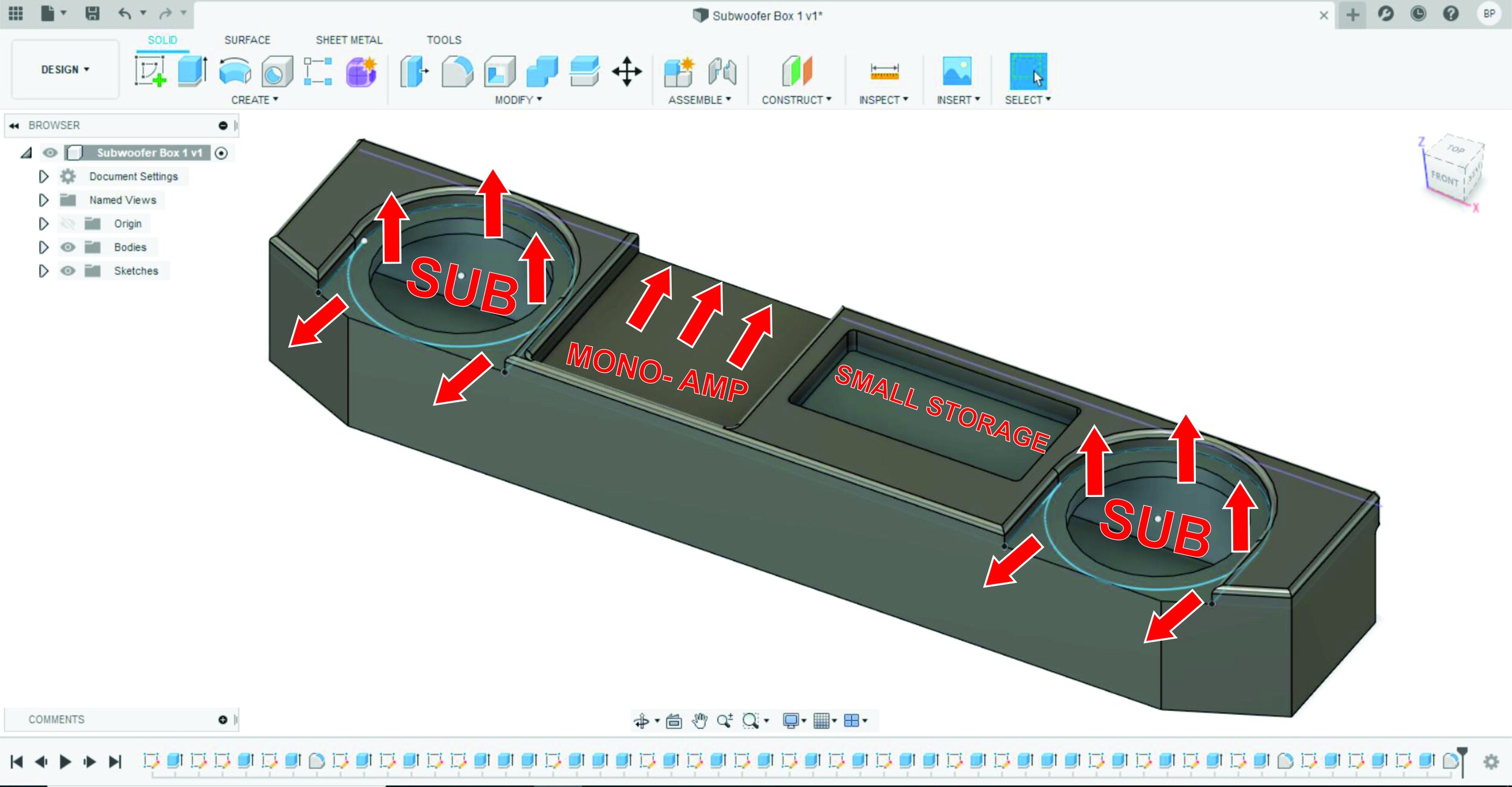

Size Constraints to Consider:
Enclosure height: 6” tall
Subwoofer cutout hole: 7” diameter
Subwoofer bezel size: 8.75” diameter
Mono-amp cutout size: 8.5” wide x 8” deep
Small storage cutout size: 12” wide x 7” deep
Mounting screws cutout size: 0.375” diameter (x4)
Pocket hole size for mounting screw brackets: 2” wide x 2.75” deep (x4)
MINIMUM air space volume: 0.5 cubic foot for each subwoofer (1 cubic foot total)
CREATE A PROTOTYPE
Almost all commercial subwoofer boxes are constructed by a well insulated material called MDF (medium-density fiberboard). It turns out that this material is also relatively cheaper than most 3/4” thick materials available in 4ft x 8ft sheets. Due to its cheap cost of around $35 per sheet, I decided to just use MDF for my first prototype to assess all of the design features I’ve made on my computer. All of the fabrication done here was on a 4’x8’ CNC milling machine (Shopbot).
Construction materials that I purchased online or at the local hardware store:
0.75”x4’x8’ MDF Sheet
Liquid Nail (Silicon)
Premium Wood Glue
Black Bedliner (DuraTex)
Textured 3" Roller & Paint Brushes
Premium Fiber Fill (32oz Bag)


Design Revision
The only design flaw on my prototype was not accommodating the height for the amplifier. I only needed to re-design the top 3 layers which I used to better “nest” the amplifier deeper into the box. Doing this revision made sure that both the box and its components attached were all under the 6 inch height requirement.
ASSEMBLY


SURFACING & SANDING


PROTECTIVE COATING


REFLECT & IMPROVE
Overall, I’m very pleased with my final design and how my sound system performs. Looking back however, there were a few minor changes that could improve the design and sound quality for future iterations.
Fitting Two 10” Subwoofers instead of Two 8” - I was being conservative by going with two 8’s because I was afraid that there wasn’t enough room for them to both fit, and sound great. 10” subwoofers typically require more air volume than the 0.5 cubic feet I designed for each of my 8’s. I now know that not only could a 10” diameter hole fit on top of this enclosure, but that using a fiber fill also increases the bass performance in the same way that more air volume does.
Prevent Rubbing from the Seat Bracket - Even though I successfully made the subwoofer box no taller than 6”, I did see that some of the rear seat’s pressure made little contact on the very back edge of the enclosure. This doesn’t affect the seat bracket or the passenger at all, but there is potential for minor scratches on the back edge of the subwoofer box. I would fix this issue in future designs by sanding down or using a router to create a deep bevel into the back edge.
Using Less Mounting Holes - The factory mounting points included x4 10mm bolts/washers. I re-purposed these same four mounting hole locations and then had to buy slightly longer bolts to get the threads to catch from my enclosure design. I realized that using all four mounting holes seemed like overkill in effectively holding down the enclosure. I would cut it down to only two bolts/mounting hole locations to cut down on some time and save a few extra dollars on hardware.

