
CNC Machining
Trinity High School was grant-funded a (Tormach 1100mx) CNC milling machine to give our students the capability of precision CNC machining. For the following months, I started experimenting with Fusion360 manufacturing software, understanding the PathPilot CNC controller, and creating new curriculum for my Fab Lab courses.

Installing the Tormach 1100mx


Trinity-Area school district ordered our 1100mx milling machine directly from the Tormach company. Our department thought it would be best located in our Metalworking shop, where we accommodated for the power requirements (Single-Phase 230 Vac, 50/60 Hz, 20A breaker) along with a compressed air line (120psi). The machine already came to us pre-assembled, so the only installation that I had to do was a putting together the metal chip tray underneath, adding machine oil, mixing/adding the coolant fluid, and mounting/squaring off the 5 inch vice with VersaGrip vise jaws. The machine itself already included the following accessories:
- Automatic Oiler
- Fogbuster Coolant Kit (Mist Coolant Capability)
- SmartCool Starter Kit (Self-Adjusting Height Nozzle for Flood Coolant)
- PathPilot Operator Console (Touchscreen Interface)
- 12-Pocket Automatic Tool Changer (Automatically Loads, Unloads, & Stores Tooling)
- MicroARC 4 (4th Axis Rotary Attachment)
- Passive Probe Kit (Automatically Sets Work Offsets)
- Electronic Tool Setter (Automatically Sets Tool Length Offsets)
Using Fusion360 Software (Manufacture)
Throughout my time as a teacher at Trinity High School, I’ve only taught my students how to use Fusion 360 in creating 3D designs and engineering drawings. This would be my first exposure in utilizing the “Manufacture” mode of the software; which programs toolpath simulations and then generates them as a G-code format that is compatible for most CNC machines. I’ve spent plenty of time reading software-specific forums and discovering amazing Youtube channels on beginner tutorials. For me personally, two of the most helpful content creators were “TITANS of CNC MACHINING” & “NYC CNC”.
To start my learning process, I’ve already designed some simple 3D models ahead of time so I can focus more on the toolpathing behaviors. Below is a simple walkthrough on key features that I’ve learned in Fusion360’s “Manufacture” mode specifically.
Creating My Tool Library:
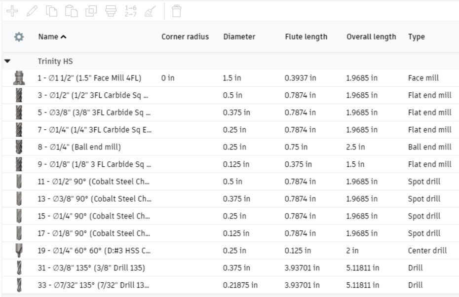
The tool library feature enabled me to create a custom library that I can streamline to all of my classes for cutting aluminum. With each tool I created, I would associate multiple cutting data parameters (feeds, speeds, & tool lengths) from the physical tooling I assembled beforehand.
Organizing My Custom Tool Library:
#1 - Face Mill
#2 - #9 - End Mills
#10 - #19 - Chamfer or Spot Drills
#30 - #39 - Drills
Creating a Setup: The setup feature is how you input where everything is located. This includes what you’re machining, the x/y/z direction/location, and the defined stock dimensions.
Creating a Toolpath: Most of the toolpaths for milling/drilling in Fusion 360 consist of five separate setup tabs: Tool, Geometry, Heights, Passes, & Linking. Below are some of the more common tool-path operations that I found myself using the most.
My Most Used Toolpath Operations
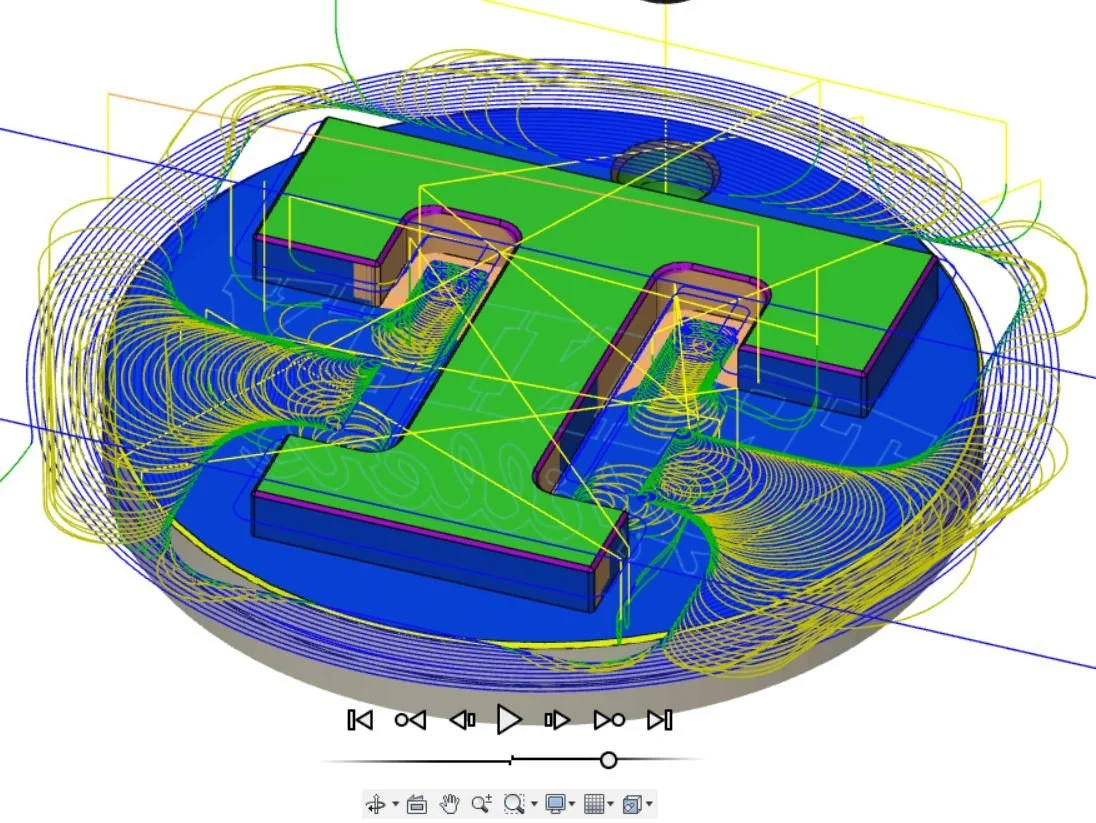
Simulating Toolpaths
I found that using this feature in Fusion 360 is a simple, easy, and accurate way to check that toolpaths are accurate and safe to run on our CNC milling machine. Each toolpath created is color coded for better visuals and makes manufacturing decisions easier for the user.
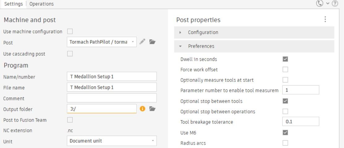
Post Processing
The Post Process tool converts any or all toolpath operations into a language (G-Code) that a CNC machine can understand. This .NC file created is then exported from Fusion 360 so it can be transferred to a CNC controller.
Using the PathPilot CNC Controller

Tormach machines have their own unique CNC controller called PathPilot. This software is what runs the G-code files and supports simultaneous motions of up to 4 axes. Since this is the first Tormach machine I’ve used, I had to learn their PathPilot software from a blank slate. I found the software easy to learn and a perfect program to expose beginners into understanding G-code. It has an intuitive touchscreen interface with overriding knobs, and has a great capability in conversational programming that lets you create programs at the machine without using Fusion 360.
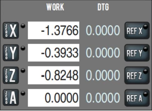
Referencing the Machine
The axes should be referenced to their home limit switches before performing any operations on the milling machine. Each axis can be referenced by pressing the “REF” buttons on PathPilot. The mill will move to its limit positions and it is advised to reference the Z-axis first to raise the head as far as possible from the work piece.
Creating My Tool Library:
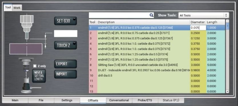
One of the first tasks I had to do was translating my Fusion360 tool library into PathPilot’s tool library. I simply plugged in all of the tool descriptions, part numbers, and diameters into their appropriate tool number slots in the offsets menu. The tool lengths however, needed to be measured on Tormach’s machine using their Electronic Tool Setter (ETS) device shown below.

Setting the Tool Length Offsets (Using Electronic Tool Setter)
An Electronic Tool Setter (ETS) is a device that sits on your machine table and acts as a switch, telling the PathPilot software when a tool touches the top of the ETS. The “offset” that is recorded is the height difference between the tip of the tooling and the face of the spindle.

Setting the Work Coordinate System (Using Passive Probe)
The work coordinate system is determined when you design your toolpaths in your CAD program. Usually the origin is set at the top center or the top back left corner of the part, but this is not necessary. I always make sure to set the work coordinate system on the machine to correspond to the work coordinate system set in the toolpath.


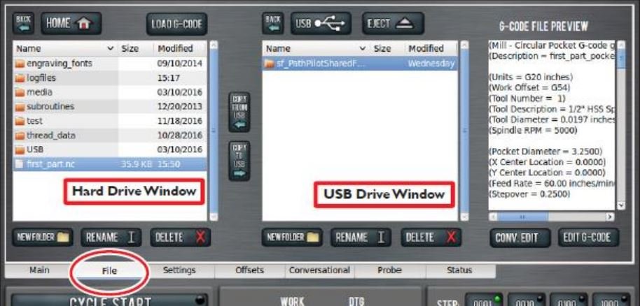
Loading G-Code
For my classroom procedure, a USB flash drive with the included .NC file will be inserted into the machine. I select my file on the USB window, and then click COPY FROM USB, which transfers it to my chosen location on the hard drive window.
Setting Up Tormach’s Tooling & Work Holding

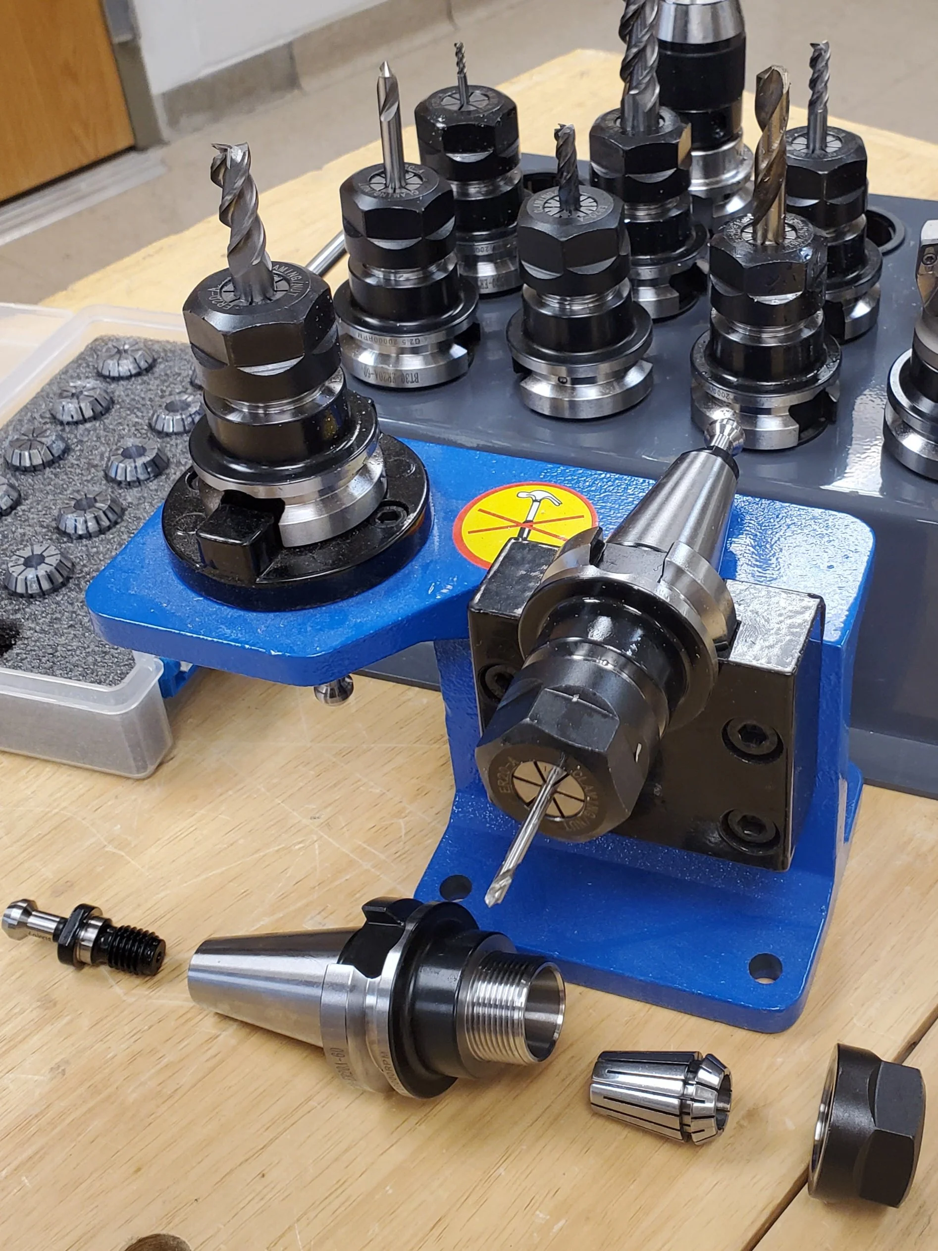
Assembling Tool Holders (BT30)
All of the cutting tools I needed to use had to be mounted into the holder and tightened so it does not move or vibrate during machining. “BT” holders have a symmetrical taper around the spindle axis. This gives the BT tooling greater stability and balance at high speeds.
I prepared the tooling by assembling the custom head onto the face mill bit, the ER20 collet heads onto our square end mills & chamfer bits, and our drill chuck heads onto our drill bits.


Work Holding (VersaGrip Vice Jaws)
To add to the versitility of machining different shapes of stock, I thought it would be best to try Tormach’s “VersaGrip™ Vise Jaws - Mitee-Bite” which would be compatible with our 5in CNC Vice. This system can accommodate a wide range of part sizes as well as holding multiple parts in a single cycle. The hardened jaws has penetrating teeth designed to bite into your workpiece, preventing lateral and horizontal movement. More importantly for me, these grips will hold circular stock so that my first project ideas were more feasible to create lessons from.
Creating New Lessons & Project Ideas
This was the time to take everything that I’ve learned for the past six months and apply them into my Fab Lab classes. I wanted to focus on simple projects that were made from aluminum to guide my classes through the process of designing 3D models, creating tool-path simulations, and operating our Tormach CNC milling machine. Below is a link to Section 2.3 of my new 2023 Fab Lab curriculum.

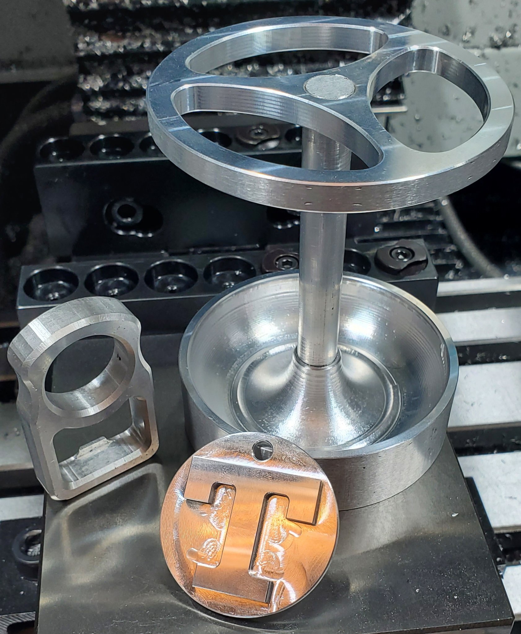
BattleBots
During the 2022-2023 school year, I helped instruct the Trinity BattleBot class in creating the aluminum frame components on our new Tormach CNC milling machine. We were also able to manufacture spare components for our Finals competition to easily swap out parts between battles.


